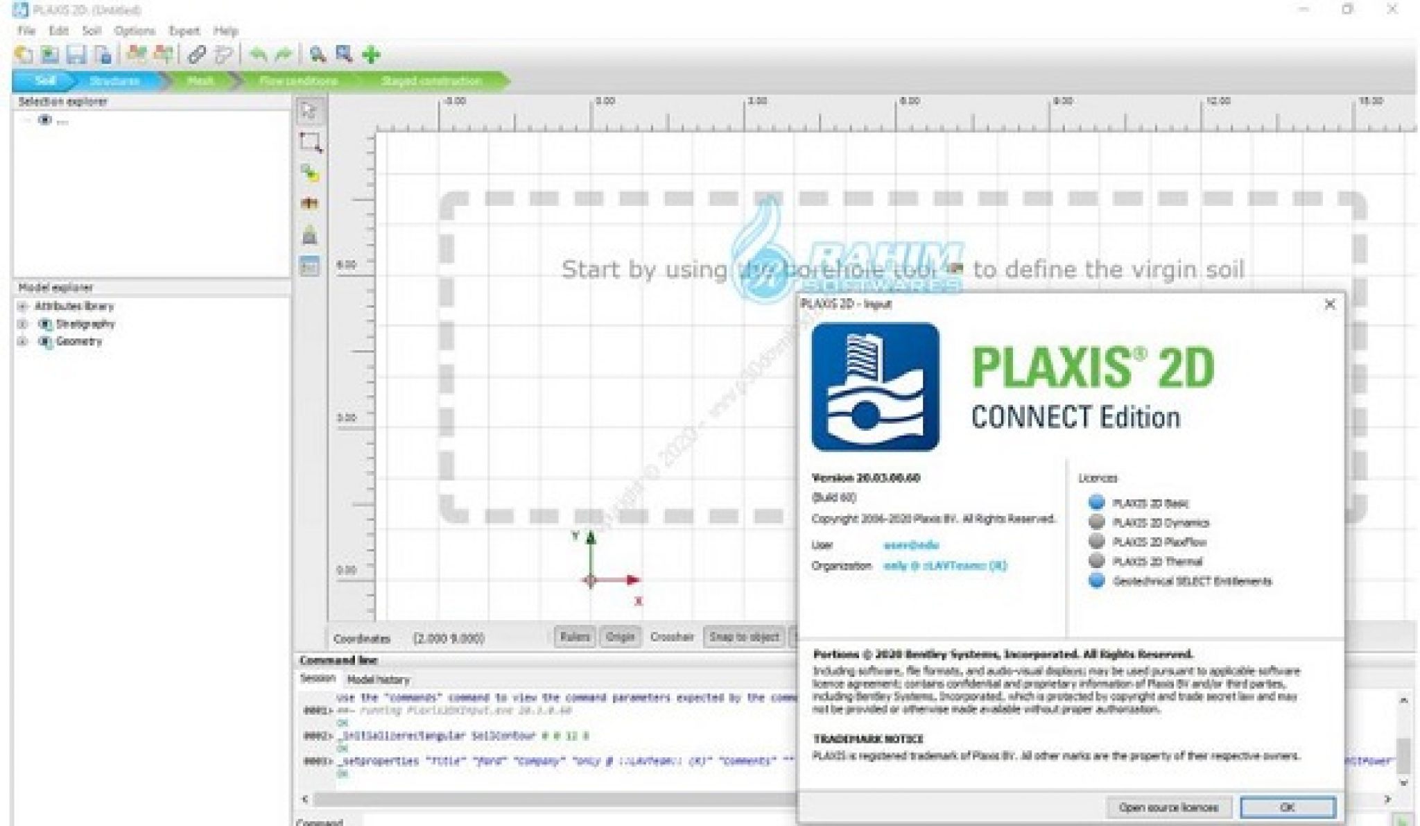
Special plate elements are used to model the bending of retaining walls, tunnel linings, shells, and other slender structures. Quadratic 6-node and 4th order 15-node triangular elements are available to model the deformations and stresses in the soil. The mesh may contain thousands of elements. Plaxis allows for fully automatic generation of unstructured finite element meshes with options for global and local mesh refinement. From this geometry model, a 2D finite element mesh is easily generated. The input of soil layers, structures, construction stages, loads and boundary conditions is based on convenient CAD drawing procedures, which allows for a detailed modelling of the geometry cross-section. With a push on a button it is also possible to represent the same data in the frequency domain, that is as a spectrum with either frequency or wave period on the x-axis.įiled under: Plaxis Dynamics | Tagged: 3d tunnel, plaxis, plaxis 3d, Plaxis 3d foundation, twoplussoft | Leave a comment » In the Curves program the results from a dynamic calculation can be shown in the time domain.
Define earthquake loads on plaxis 2d movie#
The AVI movie consists of frames created from all available output steps. With this option one can visualise for instance the development of stresses in time or the propagation of waves in the soil body. In the Output program there is an option to generate a AVI movie of most output options.

Just like any other output it is possible to view velocities and accelerations for the whole geometry at a fixed time in the Plaxis Output program or view the velocities and accelerations in time for a fixed point with the Plaxis Curves program. The dynamic time is, however, part of the total calculation time.Īdditional to the output from a static calculation the velocities and accelerations can be shown.

Therefore dynamic calculations are always performed in seconds and its output as a function of time can be viewed in what is referred to as “dynamic time”, that is the total time of all dynamic processes in seconds while long term process are discarded from the output plots. Dynamic processes however are usually measured in terms of seconds. The duration of most geotechnical processes like excavations or consolidation are measured in terms of days. A third option is the direct input of harmonic loads. For earthquake data it is possible to read data records from a SMC-file (Strong motion CD file). Input data for dynamic loads can be read from a user-defined ASCII file. Separate damping coefficients can be assigned to different material sets for both soil and structural elements Instead a Rayleigh damping term is assumed that is proportional to the mass and stiffness of the soil material.

However, in Plaxis the soil models do not include viscosity as such. Material damping in a soil is generally caused by its viscous properties, friction and the development of plasticity. Standard earthquake boundaries consist of a combination of absorbent boundaries and prescribed displacements, velocities or accelerations.įor Mohr-Coulomb and linear elastic models the wave velocities V p and V s can be entered as alternatives for the stiffness parameters. Plaxis has a convenient default setting to generate standard boundary conditions for earthquake loading. The boundary condition for prescribed displacements in static calculations has been extended such that it can be used for prescribed velocities and prescribed accelerations in case it concerns dynamic loading. To prevent the reflection of propagating waves back inside the model the boundary of the geometry can be modeled as absorbent.


 0 kommentar(er)
